

close
Choose Your Site
Global
Social Media
Views: 0 Author: Site Editor Publish Time: 2026-08-30 Origin: Site


High-pressure delivery applications—such as contrast media injection, structural heart interventions, and balloon angioplasty—push the mechanical limits of minimally invasive device architecture. Unreinforced or improperly specified polymer shafts risk catastrophic failure modes, including radial expansion, axial elongation, or burst events during clinical deployment. Balancing burst pressure resistance with 1:1 torque control and trackability requires precise engineering. Mitigating these risks requires transitioning from standard extrusions to advanced composite structures. This guide evaluates the material science, structural geometry, and manufacturing realities of specifying the optimal Braided Tube for high-pressure catheter applications. We examine how specific wire profiles, polymer matrices, and braid densities interact under extreme stress. You will learn how to navigate the trade-offs between wall thickness and internal diameter, ensuring your device meets strict anatomical access requirements without compromising fluid flow rates or structural integrity.
Burst Pressure vs. Flexibility: High pick density (PPI) and higher carrier counts (e.g., 32-carrier stainless steel) exponentially increase burst strength but introduce rigidity trade-offs that must be managed via variable durometer outer jackets.
Material Synergy is Critical: The performance of reinforced catheter tubing relies heavily on the adhesion and mechanical compatibility between the inner liner (e.g., PTFE, Polyimide), the metallic or synthetic fiber braid, and the outer polymer jacket.
Profile Optimization: Utilizing flat wire over round wire in the braid architecture allows engineers to maximize the internal diameter (ID) for fluid flow without increasing the overall French size of the catheter.
End-to-End Manufacturing Realities: Complex catheter construction requires rigorous mitigation of delamination risks, axial elongation, and the precise injection molding of proximal hubs and atraumatic distal tips.
Catheters operating under high internal pressure face unique biomechanical challenges. Viscous fluids like contrast media require rapid injection rates to achieve proper imaging resolution. According to Poiseuille's law, flow rate is directly proportional to the fourth power of the radius. Even a microscopic reduction in the internal diameter (ID) drastically cuts fluid delivery speed. This forces engineers to design shafts with ultra-thin walls that can still contain immense outward radial force.
Establishing baseline mechanical requirements dictates the entire development cycle. High-pressure applications demand strict adherence to performance metrics. You must define these targets before selecting materials or braid geometries.
Maximum Burst Pressure: Measured in atmospheres (atm) or pounds per square inch (psi). Devices must withstand pressures significantly higher than the intended clinical use. A standard angioplasty balloon shaft might require a burst rating exceeding 20 atm (294 psi).
Radial Strength: The ability of the shaft to resist expansion under internal fluid pressure or collapse under external anatomical compression.
Column Strength: Often referred to as pushability. The shaft must transmit axial force from the proximal hub to the distal tip without buckling or prolapsing in the vessel.
1:1 Torque Transmission: Rotating the proximal end must result in an identical, immediate rotation at the distal tip. This ensures precise orientation of asymmetric tips or deployment mechanisms inside the anatomy.
Kink Resistance: The shaft must maintain an open, circular lumen when navigated through tortuous anatomical routing, such as the aortic arch or the carotid siphon.
Standard polymer extrusions lack the structural integrity required for high-pressure fluid delivery. Relying on unreinforced tubing introduces severe clinical risks. Understanding these failure mechanisms highlights the necessity of composite architecture.
Failure Mode | Mechanism of Action | Clinical Consequence |
|---|---|---|
Ballooning (Radial Yield) | Internal pressure exceeds the polymer's yield strength, causing localized radial expansion. | Creates a weak point, disrupts fluid dynamics, and can prevent device withdrawal through the introducer sheath. |
Axial Elongation | Pressure forces the polymer matrix to stretch longitudinally. | The catheter "snakes" inside the vessel, losing positional accuracy and potentially damaging the vessel wall. |
Complete Rupture | The polymer wall breaches entirely under peak injection pressure. | Releases fluid or contrast media outside the intended target area, presenting severe patient safety risks. |
Kinking | Bending radius exceeds the material's structural limit, collapsing the lumen. | Blocks fluid flow entirely and permanently damages the catheter shaft. |
Composite catheter construction solves the limitations of single-layer extrusions by encapsulating a structural reinforcement layer between two distinct polymer layers. This tri-layer design fundamentally changes how the shaft handles mechanical stress.
The inner liner provides a lubricious pathway for fluids or secondary devices. The middle reinforcement layer acts as the structural backbone. It absorbs and distributes radial stress across the entire shaft, preventing the inner liner from expanding. The outer jacket provides the necessary flexibility, environmental protection, and atraumatic surface. Together, these layers prevent localized mechanical failure and enable high-pressure containment within a minimal wall thickness.
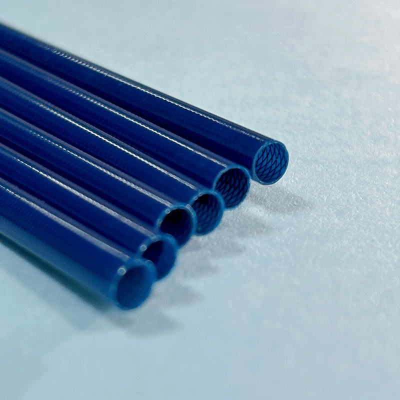
Selecting the right reinforcement geometry dictates the mechanical behavior of the catheter. Engineers must choose between different patterns, densities, and materials to achieve the desired performance profile.
The fundamental geometry of the reinforcement layer determines its primary strengths. Braids and coils offer distinctly different mechanical advantages. Selecting between them depends on the specific clinical application.
A braided structure consists of wires woven in an over-under pattern. This geometry provides superior torque control and high burst pressure resistance. It offers bidirectional stability, meaning it performs consistently regardless of clockwise or counter-clockwise rotation. Braids excel in applications requiring precise manipulation and high-pressure fluid delivery.
Coil reinforcement involves winding a single wire helically along the shaft. Coils deliver maximum flexibility and superior crush resistance. However, they inherently possess lower burst thresholds compared to braids because they lack interlocking cross-wires to contain radial expansion. They also lack 1:1 torque transmission; rotating against the coil direction causes the structure to unwind and expand.
Hybrid approaches combine both geometries. A braid-over-coil design provides extreme kink resistance alongside high-pressure containment. This complex architecture is reserved for highly specialized devices, such as mechanical thrombectomy aspiration catheters, where neither a standalone braid nor a standalone coil suffices.
Braid density is measured in Picks Per Inch (PPI) or Picks Per Centimeter (PPCM). This metric defines how tightly the wires are woven. Adjusting the PPI allows engineers to tune the mechanical properties of the shaft.
A high PPI creates a dense wire matrix. This maximizes pressure resistance and hoop strength. However, it significantly reduces the flexibility of the catheter. A low PPI increases trackability and flexibility but sacrifices burst strength. Engineers often vary the PPI along the length of the shaft during the braiding process. This creates a stiff proximal section for pushability and a flexible distal tip for navigation.
Carrier counts refer to the number of individual wires used in the braiding machine. Common configurations include 16, 32, 48, 64, 96, and 144 carriers. Higher carrier counts distribute stress more evenly across the catheter shaft. A 32-carrier or 64-carrier braid achieves superior burst ratings compared to a 16-carrier setup. It allows for a tighter weave using finer wires without excessive wire overlap, keeping the overall wall profile thin.
Braid angles also play a direct role in performance. The angle at which the wires intersect affects axial elongation. A higher braid angle (closer to 90 degrees relative to the longitudinal axis) improves burst strength but increases the risk of the catheter elongating under pressure. A lower angle improves axial stability but reduces radial containment.
The material and shape of the braiding wire directly impact the final dimensions and strength of the catheter. Material selection must align with the required burst thresholds and clinical environment.
Wire Material | Key Mechanical Benefit | Common Clinical Application |
|---|---|---|
304V / 316LVM Stainless Steel | Industry standard for maximum tensile strength and burst resistance. High modulus of elasticity. | High-pressure contrast injection, balloon angioplasty, structural heart delivery systems. |
Nitinol (Nickel-Titanium) | Superelasticity, shape memory properties, and extreme kink resistance. | Tortuous anatomy navigation, neurovascular microcatheters, peripheral crossing catheters. |
Tungsten / Platinum Iridium | High radiopacity for fluoroscopic visibility. | Marker bands, distal tip reinforcement for imaging contrast. |
Synthetic Fibers (Kevlar, Vectran, UHMWPE) | High tensile strength, non-metallic, MRI compatibility, zero radiopacity. | MRI-guided interventions, electrophysiology mapping catheters. |
Beyond material, the geometric profile of the wire dictates the wall thickness. Engineers typically choose between round wire and flat wire. Round wire is cost-efficient and offers distinct structural rigidity advantages. It is easier to source, handles tension well during braiding, and provides excellent column strength.
Flat wire minimizes the wall thickness of the reinforcement layer. By flattening the wire (e.g., 0.001" x 0.003"), engineers maximize the internal lumen capacity without increasing the outer diameter. This is mandatory when designing devices constrained by strict anatomical access limits, where every thousandth of an inch impacts fluid flow rates.
The polymer layers encapsulating the braid are just as critical as the metal itself. The inner liner and outer jacket must work in synergy to provide lubricity, flexibility, and pressure containment.
The inner liner dictates the internal friction of the catheter. It must allow fluids or secondary devices to pass smoothly. PTFE (Polytetrafluoroethylene) is the gold standard for maximum lubricity. It provides an exceptionally low coefficient of friction. However, PTFE is notoriously difficult to bond with other polymers. It requires chemical etching—typically using a sodium naphthalene solution—to strip fluorine atoms from the surface, creating a carbon-rich layer suitable for adhesion.
For applications demanding extreme burst resistance prior to the reinforcement layer, engineers turn to alternative materials. Integrating PI braided medical tubing utilizes Polyimide as the base structure. Polyimide offers ultra-thin walls (down to 0.0005"), high dielectric strength, and exceptional mechanical stability. It is highly resistant to pressure expansion and does not require chemical etching for adhesion, making it an ideal substrate for high-pressure microcatheters.
The outer jacket protects the braid and interacts directly with the patient's anatomy. It must provide a smooth, atraumatic surface while contributing to the overall mechanical strength of the shaft.
Specifying braided PEBAX tubing is a dominant strategy in catheter design. PEBAX (polyether block amide) allows engineers to create variable durometer segments along the shaft. You can use a high-durometer (stiff, e.g., 72D) PEBAX at the proximal end for pushability. You can then transition through mid-range grades (55D, 40D) to a low-durometer (soft, e.g., 35D) PEBAX at the distal tip for atraumatic navigation. This continuous outer layer is fused over the braid during the thermal reflow process.
Alternatives include Nylon 12 and Polyurethanes. Nylon 12 offers excellent burst strength augmentation and strong adhesion properties, often used in high-pressure balloon shafts. Polyurethanes provide superior flexibility and biocompatibility, often used in long-term implantable devices or highly tortuous routing where PEBAX might kink.
Not all applications require the extreme burst strength of a braided structure. In specific use cases, engineers may select spring reinforced PE tubing over traditional braided architectures.
Polyethylene (PE) combined with a spring coil provides excellent cost-efficiency. It meets specific flexibility requirements where kink resistance is prioritized over high-pressure containment. This architecture is often chosen for large-bore aspiration catheters, urology drainage tubes, or guide sheaths operating under lower-pressure thresholds. It allows for rapid manufacturing and reliable performance in less demanding fluid delivery scenarios.
Designing high-pressure catheters involves constant compromise. Improving one mechanical property often degrades another. Engineers must navigate these trade-offs to achieve a balanced, functional device.
Catheter dimensions are strictly constrained by the anatomy. The outer diameter (OD) is measured in French size (1 Fr = 0.33mm). Exceeding the target French size prevents the device from entering the designated introducer sheath or blood vessel.
The engineering challenge lies in maximizing the internal diameter (ID) for fluid passage while maintaining this strict OD. Thicker walls improve burst strength but restrict flow rates. Utilizing flat wire braids and ultra-thin Polyimide liners helps engineers reclaim valuable cross-sectional area without sacrificing structural integrity. For example, switching from a 0.002" round wire to a 0.001" x 0.003" flat wire saves 0.002" on the overall OD, which can be reallocated to the ID.
Many advanced devices require multiple internal channels. One lumen may deliver contrast media, while another houses a pull wire, sensor, or guidewire. Braiding over multi-lumen extrusions introduces significant manufacturing complexities.
The primary risk is lumen collapse during the high-heat jacket reflow process. The pressure exerted by the heat shrink tubing can distort the internal geometry. To mitigate this, manufacturers insert solid mandrels (typically silver-plated copper or acetal) into each lumen before reflow. These mandrels maintain the precise shape of the channels under extreme heat and pressure. They are removed only after the polymer has fully cooled and cured.
A catheter must reach its target efficiently. This requires a delicate balance between column strength and flexibility. If the shaft is too stiff, it will cause trauma to the vessel walls or fail to navigate sharp turns. If it is too soft, it will buckle under the physician's hand.
Integrating reinforced catheter tubing provides the necessary framework to balance these forces. The braid provides the column strength required to advance the device. The variable durometer outer jacket provides the flexibility needed to navigate tortuous vasculature. Kink resistance is maintained by the structural support of the wire matrix, ensuring the lumen remains open even when bent at acute angles.
Transitioning a catheter design from a CAD model to a physical product involves complex manufacturing processes. Understanding these realities helps engineers design for manufacturability and avoid costly late-stage failures.
Composite shafts rely entirely on the bond between their layers. Delamination occurs when the inner liner, braid, and outer jacket separate under repeated stress or high-pressure cycling. This destroys the mechanical integrity of the device, leading to immediate ballooning or burst.
Mitigation strategies are mandatory during manufacturing. Plasma treatment activates the surface of inert polymers, improving chemical bonding. Tie layers—ultra-thin extrusions of highly adhesive polymers like Tecoflex—can be applied between the liner and the jacket. Optimized thermal reflow parameters ensure the outer jacket melts completely through the braid interstices to fuse directly with the etched inner liner. The reflow process typically uses FEP heat shrink, which compresses the melting jacket at temperatures around 400°F before being scored and removed.
High internal pressure forces the catheter to expand radially. Because the braided wires are interwoven, this radial expansion causes the wires to shift, resulting in axial elongation. The catheter effectively lengthens inside the body.
If the braid angle and polymer matrix are not properly constrained, this elongation causes severe clinical complications. Techniques for axial reinforcement include integrating longitudinal pull wires alongside the braid. Incorporating specific high-tensile synthetic fibers (like Kevlar) running parallel to the shaft limits longitudinal stretching without compromising radial flexibility.
A catheter requires a proximal hub for luer locks and injection ports, and an atraumatic distal tip for safe navigation. Integrating these components requires precision injection molding and thermal bonding.
The critical process involves overmolding the proximal hub directly onto the reinforced shaft. The molding temperature must be high enough to fuse the materials but low enough to avoid melting the shaft's inner liner or collapsing the lumen. Fusing a soft, unreinforced distal tip to the braided section requires precise thermal bonding using RF or laser welding. Any weakness at these junction points creates a prime location for high-pressure burst failures.
Transitioning from R&D prototyping to high-volume manufacturing introduces new challenges. A process that works for ten prototypes may fail when scaled to ten thousand units.
Managing lead times for custom braid configurations is critical. Specialized wire profiles and high-carrier braiding machines require significant setup time and tension calibration. Engineers must focus on minimizing scrap rates during the extrusion, braiding, and reflow phases. Strict process controls, automated laser micrometer inspection systems, and rigorous operator training maintain yield optimization and keep unit costs viable.
Medical devices operating under high pressure face strict regulatory scrutiny. Proving the safety and efficacy of the catheter requires comprehensive testing and documentation.
Establishing burst pressure ratings requires standardized testing protocols, heavily guided by ISO 10555 standards for intravascular catheters. Static burst testing involves capping the distal end and injecting fluid at a controlled ramp rate until the shaft ruptures. This establishes the absolute maximum pressure limit.
Clinical use involves pulsatile flow and repeated stress. Fatigue testing under pulsatile conditions simulates the repeated stress of multiple contrast injections. Devices must be conditioned in a 37°C saline bath prior to testing to accurately replicate in-vivo material behavior, as polymers soften significantly at body temperature. These protocols ensure the established clinical safety margins are accurate and reliable.
All materials used in the composite structure must meet strict biocompatibility standards. ISO 10993 compliance is mandatory for the selected polymers, metals, and colorants. This ensures the device does not elicit an adverse biological response, cytotoxicity, or systemic toxicity during patient contact.
Composite medical device manufacturing requires absolute material lot traceability. Every spool of wire, batch of polymer resin, and length of heat shrink must be documented in the Device History Record (DHR). In the event of a field failure, manufacturers must be able to trace the exact origin of every component within the affected device to execute targeted recalls and root cause analysis.
To move forward with your high-pressure catheter development, execute the following steps:
Define exact OD/ID constraints and required burst thresholds in atm or psi based on your specific clinical application.
Establish flexibility gradients for the proximal shaft and distal atraumatic tip to map out your PEBAX durometer transitions.
Select inner liner materials based on the specific lubricity requirements of the device payload and the required wall thickness.
Specify flat wire over round wire if your design requires maximizing the internal lumen within a strict French size limit.
Consult with a specialized extrusion and braiding contract manufacturer to initiate the prototyping phase and validate your reflow parameters.
A: A braided tube significantly increases burst pressure resistance, column strength, and 1:1 torque transmission without proportionally increasing the wall thickness or sacrificing all flexibility.
A: Braided PEBAX tubing allows engineers to vary the durometer of the outer jacket along the length of the catheter, providing proximal pushability and distal trackability over a continuous braided shaft.
A: PI braided medical tubing is ideal for applications requiring ultra-thin walls, high burst strength, and high chemical or thermal resistance, often used in neurovascular or cardiovascular microcatheters.
A: Spring reinforced PE tubing provides excellent kink and crush resistance with maximum flexibility, whereas braided tubing is optimized for high burst pressure, axial stability, and torque transmission.
A: Flat wire reduces the overall wall thickness of the reinforcement layer, allowing for a larger internal diameter within the same French size, whereas round wire provides different structural rigidity and cost efficiencies.
A: PTFE is highly lubricious and chemically inert, meaning it will not naturally bond to outer polymer jackets. Chemical etching alters its surface chemistry, allowing it to fuse securely during the thermal reflow process.


